by Wikibooks, open books for an open world
Available in 123 free installments
Owner:
In acoustic transducers, media coupling is employed in acoustic transducers to either increase or decrease the impedance of the transducer, and, thus, control the intensity and speed of the signal acting on the transducer while converting the incident wave, or initial excitation sound wave, from one form of energy to another (e.g. converting acoustic energy to electrical energy). Specifically, the impedance of the transducer is augmented by inserting a solid structure (not necessarily rigid) between the transducer and the initial propagation medium (e.g. air). The reflective properties of the inserted medium is exploited to either increase or decrease the intensity and propagation speed of the incident sound wave. It is the ability to alter, and to some extent, control, the impedance of a propagation medium by (periodically) inserting (a) solid structure(s) such as thin, flexible films in the original medium (air) and its ability to concomitantly alter the frequency response of the original medium that makes use of multilayer media in acoustic filters attractive. The reflection factor and transmission factor  and
and  , respectively, between two media, expressed as...

and
 ,
,
are the tangible values that tell how much of the incident wave is being reflected from and transmitted through the junction where the media meet. Note that  is the (total) input impedance seen by the incident sound wave upon just entering an air-solid acoustic media layer. In the case of multiple air-columns as shown in Fig. 2, is the aggregate impedance of each air-column layer seen by the incident wave at the input. Below in Fig. 1, a simple illustration explains what happens when an incident sound wave propagating in medium (1) and comes in contact with medium (2) at the junction of the both media (x=0), where the sound waves are represented by vectors.
As mentioned above, an example of three such successive air-solid acoustic media layers is shown in Fig. 2 and the electroacoustic equivalent circuit for Fig. 2 is shown in Fig. 3 where  = (density of solid material)(thickness of solid material) = unit-area (or volume) mass,
  characteristic acoustic impedance of medium, and
 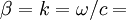 wavenumber. Note that in the case of a multilayer, coupled acoustic medium in an acoustic filter, the impedance of each air-solid section is calculated by using the following general purpose impedance ratio equation (also referred to as transfer matrices)...
where  is the (known) impedance at the edge of the solid of an air-solid layer (on the right) and
  is the (unknown) impedance at the edge of the air column of an air-solid layer.
